Find the hotspot before it finds your yield report.

Radiometric thermal + RGB drone survey detects hotspots, PID, bypass diode failure and micro-cracks that manual walkthroughs miss then tracks every defect to resolution on a live dashboard, not just a PDF. DGCA-certified. IEC 62446-3 compliant. Zero shutdown.

5+ lakh
Drone Flights Completed
34+ GW
Solar Assets Inspected
2.3+ lakh
Hectares Surveyed

210+ Cr

Saved in Operational Costs

13,000+

Rooftop Surveys Completed
What Is It

Drone Solar Panel Inspection

Drone solar panel inspection also called aerial thermography for solar PV, or UAV photovoltaic inspection uses radiometric thermal UAVs to scan entire arrays from above, capturing the temperature anomalies that indicate module-level defects. A DGCA-licensed pilot flies a calibrated grid pattern over each panel row, recording thermal and visible-light imagery in the same pass. The processed output is a geo-tagged defect map, an IEC 62446-3 compliant report, and uniquely at Lesoko. A live dashboard your team can log into.

Manual walkthroughs catch surface damage only. I-V curve tracing finds electrical faults but needs partial shutdown and heavy field time at scale. Aerial thermography covers a utility-scale asset in a fraction of the time, surfacing the defects both older methods routinely miss while the plant keeps generating.

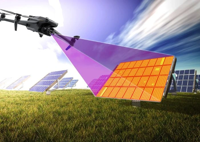
Drone projecting thermal scan beam onto single solar panel showing orange cell-level heat overlay during inspection
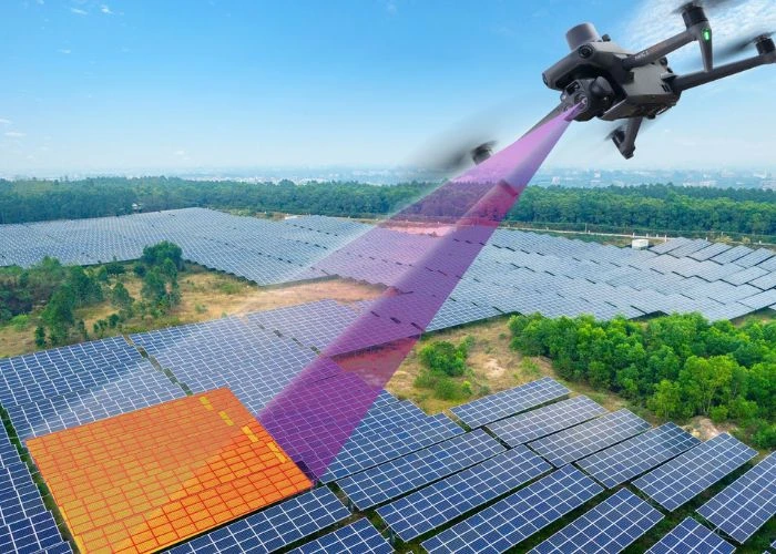
Drone projecting thermal scanning beam over utility-scale solar farm with orange heat overlay on scanned panel section
The Gap

What manual inspection and SCADA both miss

Manual inspection works for post-storm visual assessment. It does not catch early-stage hotspots, PID degradation, or bypass diode faults across thousands of modules and string-level underperformance rarely shows up in SCADA until the cumulative loss is already operationally significant.

Why the loss stays invisible

Unresolved bypass diode failures cause progressive yield loss that compounds for months before SCADA reporting triggers action. Field inspection at scale carries real safety exposure too rooftop access requires fall protection and permit-to-work processes most O&M teams would rather avoid running routinely.

Without module-level, geo-tagged documentation, lender audits and manufacturer warranty claims lack the evidence base they require which is exactly the gap a radiometric thermal survey closes.

Radiometric vs Non-Radiometric

Radiometric sensors record an absolute temperature value per pixel, enabling defect classification by exact temperature differential. Lesoko deploys 640×512 resolution sensors with 0.05°C thermal sensitivity, capturing heat anomalies invisible to standard cameras.

Non-radiometric thermal cameras only show relative heat patterns and cannot produce IEC 62446-3 compliant output. The distinction that decides whether a report is acceptable to a lender, insurer, or independent technical auditor.

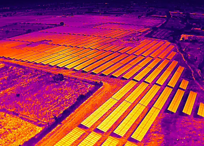
Radiometric thermal aerial image of utility-scale solar farm showing panel arrays in yellow-orange against purple cooler terrain
Process

How the inspection process works

Six operational steps from pre-flight planning to report delivery. Every stage is designed around one constraint: zero production downtime.

 
1

Pre-Flight Planning

Survey date confirmed with the site representative, DGCA no-fly zone check, weather-window verification, and flight-path design against the array layout.

4

Thermal + Visual Capture

RGB mapping at 80% front / 70% side overlap, ~6.5 m/s. Thermal mapping at the same overlap ratios, ~1.7 m/s, altitude set by roof or array height. Both datasets geo-tagged at module level.

2

Site Risk Assessment

On-site toolbox talk with client personnel, blocks/trackers requiring inspection re-confirmed, obstacle survey (altitude raised 15 m above any obstruction).

5

Defect Analysis

Engineer-led thermal anomaly detection and IEC 62446-3 severity classification. Visible-light imagery is overlaid on thermal data to eliminate soiling-driven false positives before the register is finalised.

3

Flight Execution

Licensed pilot flies under IEC 62446-3 irradiance conditions (600+ W/m², or panel temperature above 30°C). Flights parallel to panel rows with a 10 m overlap between KML boundaries.

6

Report + Dashboard Delivery

Engineer-verified output within 24 hours: geo-tagged defect maps, maintenance prioritisation sheets, executive dashboard, and live access to the Lesoko defect-tracking platform.

Defect Detection

Defects detected by aerial thermography

Radiometric thermal sensors identify twelve distinct fault categories across Lesoko’s inspection history. Every one causes measurable production loss or safety risk, and none are visible to the naked eye until they’ve already compounded.

 
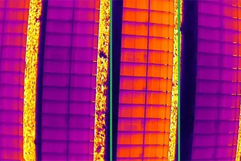
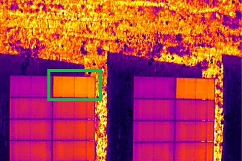
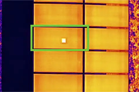
Radiometric thermal image of solar panel with single cell-level hotspot highlighted by green bounding box

Hotspot​

Cell-level temperature spike from mismatch, micro-cracks or partial soiling. Elevates fire risk and degrades string output progressively if unresolved.
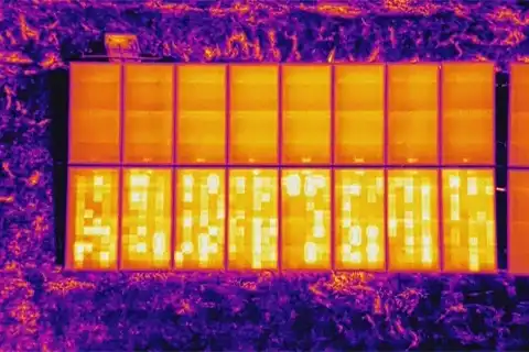
Aerial thermal image showing multiple distributed hotspot anomalies across solar panel strings

Multiple hotspot​s

Two or more hotspot zones within a single module, indicating advanced cell degradation or sustained mismatch.
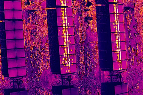
Aerial thermal image showing string reverse polarity fault with bright cell clusters across lower panel row

String Reverse Polarity

Positive and negative connections of a string reversed at the combiner box current flows backwards, dissipating the string's power as heat.
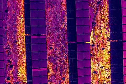
Radiometric thermal image showing open circuit fault with irregular hotspot pattern across solar panel strings

Open Circuit

A break or disconnect in the electrical path. No current, no heat signature. The affected module or string produces zero output.
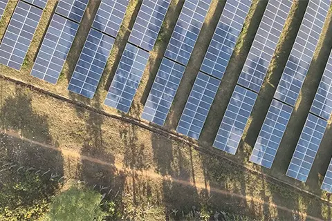
Aerial view of solar farm rows with diagonal shadow shading cast across multiple panel strings

Shadow & Shading

Objects or structures casting shade on modules, reducing efficiency and inducing reverse-bias stress on shaded cells.
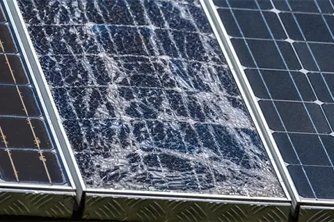
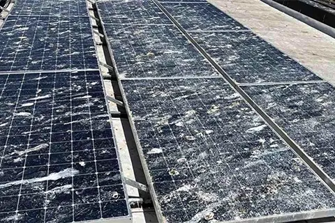
Close-up of solar panel with severely shattered glass across full module surface between undamaged panels

Damage

Glass breakage, cell cracks or frame damage compromising module integrity increases arc-fault risk and reduces generation capacity.
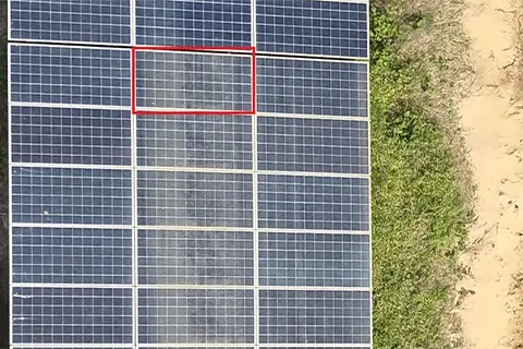
Aerial view of solar panels with visible dust and soiling streaks, one soiled module highlighted in red

Dust & Soiling

Particulate accumulation reducing irradiance absorption. The #1 efficiency loss factor in India's dry climate, seen heavily in Rajasthan and Gujarat.
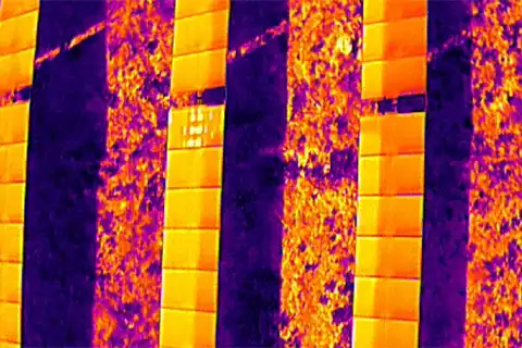
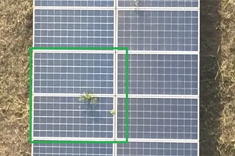
Aerial view of vegetation growing through ground-mounted solar panels, highlighted with green bounding box

Vegetation Overgrowth

Plant growth causing persistent shading, structural stress and fire risk in ground-mount systems common at sites with lapsed vegetation management.
Aerial view of rooftop solar panels with heavy bird dropping contamination across multiple modules and frames

Bird Droppings

Localised shading and contamination that accelerates cell-level degradation particularly prevalent at coastal and floating solar sites.
Key Benefits

Why Solar Asset Owners Choose Aerial Thermography

Reasons why O&M managers, EPC heads, and IPP procurement teams specify Lesoko for their solar PV inspection programmes.

Lender-grade documentation

Geo-tagged defect evidence and IEC 62446-3 documentation formatted for direct use in technical due diligence.

Module-level GPS tagging

Every anomaly geo-tagged with exact coordinates so maintenance teams locate defects without re-inspection.

Live defect dashboard

Track every defect from detection through resolution not a one-time PDF that goes stale the day it's opened.

Preventive, not reactive

Scheduled surveys catch defects before they compound well ahead of the SCADA alert that signals loss already accrued.

Zero production downtime

Panels stay energised throughout the survey. A technical requirement for accurate defect detection, not a constraint.

₹210+ Cr proven ROI

Operational savings enabled across Lesoko's inspection portfolio, measured against revenue lost to unresolved anomalies.

Radiometric, IEC 62446-3 output

Temperature-accurate data (not visual-only imagery) meeting the sensor and documentation standard lenders require.

24-hour engineer-verified reports

Industry standard turnaround is 3–7 days. Lesoko delivers within 24 hours of flight completion, every time.

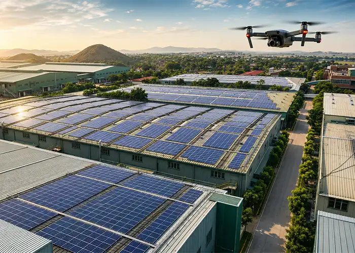
DJI drone flying over large industrial complex with rooftop solar panels installed across multiple warehouse buildings
Technical Methodology

Inspection Methodology

Inspections are scheduled during peak irradiance windows 600+ W/m² is the minimum threshold for reliable defect detection. Thermal sensors undergo radiometric calibration before each session; ambient temperature, wind speed, and humidity are logged throughout the flight.

Ground sampling distance (GSD) is calibrated per site flight altitude is adjusted to achieve sub-5 cm/pixel resolution at module level, enabling individual cell defect identification rather than row-level anomaly detection only. Flight operations are suspended when wind speed exceeds 8 m/s beyond this threshold, radiometric sensor accuracy and UAV flight stability are both compromised.

Post-flight, thermal and visible-light imagery is processed into georeferenced orthomosaics using photogrammetry software. Defect classification follows IEC 62446-3 severity tiers. Engineer-led thermal anomaly detection eliminates false positives before the defect register is finalised. Every anomaly is reviewed by a qualified engineer before entering the final report.

Site-Specific Variables That Affect Thermal Data Quality

Soiling False Positives

Soiling deposits closely resemble early-stage hotspot defects in thermal imagery. Engineers overlay visible-light imagery over thermal data to eliminate soiling-induced false positives before the defect report is issued.


Tracker Tilt & Single-Axis Systems

Single-axis tracker panels require inspection at fixed tilt angles during peak irradiance. Tracker position is coordinated with plant operations before flight scheduling on all tracker-equipped sites.


Sun Angle & Irradiance Timing

Radiometric data quality degrades when sun angle is below 30° from horizontal. Inspection flights are scheduled around peak irradiance windows typically mid-morning to early afternoon.


Inverter Mismatch Overlap

Inverter mismatch signatures can overlap with electrical fault thermal patterns. All Lesoko reports include engineer-reviewed classification before final defect register issuance to distinguish these accurately.

 
Who This Is For

Built for the people who answer for plant performance

Solar O&M Managers

EPC Heads (Renewable Energy)

IPPs & DISCOMs

Coverage across every major solar cluster

Lesoko deploys within 48 hours for sites above 10 MW. Completed inspection projects span Tamil Nadu, Karnataka, Gujarat, Rajasthan, Maharashtra, Andhra Pradesh and Telangana including Charanka (Gujarat), Bhadla (Rajasthan), Pavagada (Karnataka), Kurnool Ultra Mega Solar Park (Andhra Pradesh) and the Kamuthi Solar Power Project (Tamil Nadu).

Same-day deployment is available in Chennai, Bengaluru and Hyderabad.

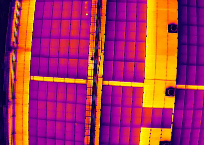
Aerial radiometric thermal image of rooftop solar panels showing purple-orange temperature variation across the array
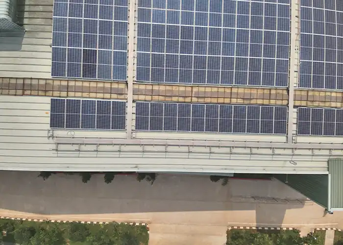
Aerial photo of rooftop solar panel rows along a building edge with maintenance walkway and ground visible below

Regional note: arid vs coastal sites

Dust accumulation patterns differ sharply between arid sites (Rajasthan, Gujarat) and coastal installations (Tamil Nadu, Kerala). Arid sites see higher soiling false-positive rates; coastal and floating sites carry elevated junction box corrosion and bird-drop risk. Inspection protocols are adjusted per region.

Monsoon season restrictions

Drone operations across peninsular India are restricted June–September due to monsoon wind and rainfall. Pre-monsoon (March–May) and post-monsoon (October–November) windows deliver the most operationally useful data.

Pricing

Inspection cost and pricing structure

Drone solar panel inspection pricing is project-specific. No two sites share identical requirements. Larger sites benefit from lower per-MW cost due to deployment efficiency and multi-site portfolios within a region can reduce costs further.

Sites within the same state or region can be bundled into a single mobilisation reducing per-MW cost considerably across the portfolio. Inspection spend is typically a small fraction of the operational savings enabled by early defect detection. ₹210 Cr+ in operational savings has been enabled across Lesoko’s inspection portfolio measured by early defect resolution against estimated revenue loss from unresolved production anomalies. Inspection reports are formatted for direct use in lender technical due diligence, reducing documentation overhead for EPC and IPP procurement teams.

Pricing variables that determine inspection scope and cost

Proven Results
Real Projects.
Measurable Impact.
📍 Andhra Pradesh · 600KW Rooftop Solar Plant

A 600KW rooftop solar power plant was inspected after reporting a steady drop in output. Regular dust accumulation was the primary suspected cause. Lesoko's drone flew for just 1.5 hours and delivered cell-level defect mapping across all 1,430 modules — enabling the O&M team to take same-day action.

Capacity
600 KW
Modules
1,430 NOS
Module Type
Mono Crystalline
Flight Duration
1.5 Hours

Outcomes Achieved

185KW total loss identified across 4 defect categories
148KW (80%) immediately recovered after cleaning + shadow removal
₹1,036/day in generation savings recovered
30% → 24% loss reduction — O&M team revised maintenance frequency

Defect Breakdown — % of 600KW

Soiling
80KW · 13.3%
Bird Drop
51KW · 8.5%
Hotspot
37KW · 6.1%
Shadow
17KW · 2.8%

Solar Panel Inspections Video Coverage

Our Amazing Clients

What Solar Plant Operators Say

We have had the opportunity to collaborate with Lesoko Technologies Pvt. Ltd. on multiple projects involving Rooftop Surveys, Topography Mapping, and Solar Thermal Inspection services. The experience of working with your team has been highly professional and technically impressive. Your team consistently delivered accurate survey data, high-quality mapping outputs, and detailed thermal inspection reports, which played a crucial role in project planning, defect identification, and performance assessment. The clarity of deliverables, strong technical expertise, and efficient coordination demonstrated by your team ensured smooth project execution across all assignments. Based on our experience, Lesoko Technologies Pvt. Ltd. has proven to be a dependable and technically capable partner for solar survey and inspection services, contributing significantly to the successful execution of our solar projects.

SKS Cleantech Pvt Ltd Sundar Iyer
Deliverables

What Every Inspection Includes

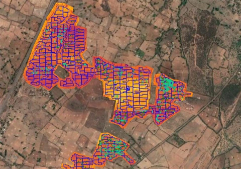
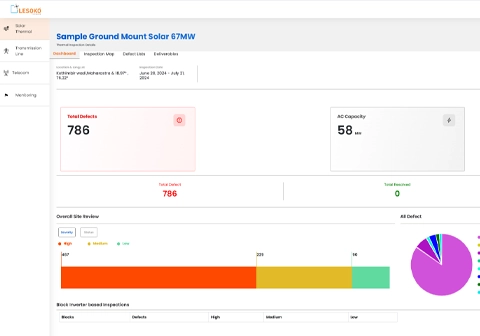
Lesoko inspection dashboard showing 786 total defects across 67MW Maharashtra solar site with severity breakdown by high, medium and low

Defect Layout (AutoCAD)

CAD-generated PDF mapping every defect to its exact location in the plant layout.
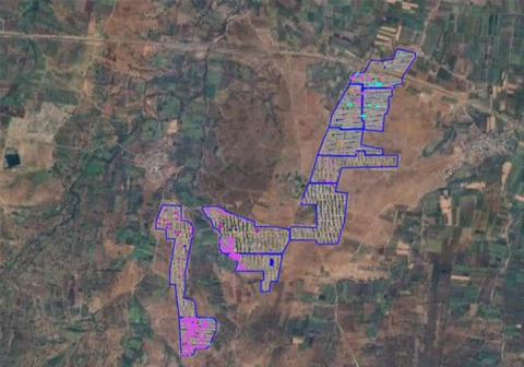
Georeferenced orthomosaic of 67MW solar site with blue boundary outline over satellite base map showing full array layout

KML Report

Google Earth file plotting every defect location alongside IR and RGB reference imagery.
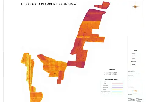
Lesoko printed thermal defect map of 67MW ground mount solar site showing full array boundary with defect classification legend

Cumulative Report

Combined IR and RGB imagery per defect for direct visual verification in the field.
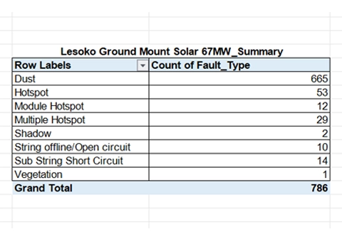
Lesoko defect list showing 786 panel-level faults with GPS coordinates, criticality ratings and priority for 67MW solar site

Defect Report (Excel)

Full defect list with row number, block/tracker number and fault type filterable and sortable.
Radiometric thermal orthomosaic of solar panel rows showing orange-amber heat tones with individual cell structure visible

Inspection Map

RGB, thermal and grayscale overlay view with panel-ID search and full-screen mode for field teams.
Lesoko inspection dashboard showing 786 total defects across 67MW Maharashtra solar site with severity breakdown by high, medium and low

Project Summary

Data acquisition methodology, weather conditions, and severity analysis in one overview document.

Get Free Quote in 24 Hours

Free · No obligation · Quote in 24 hours
 

Phone/ Whatsapp

+91 78457 26375/ 7845726374

Email Us

sales@lesoko.in

Head Office

T. Nagar, Chennai, Tamil Nadu 600017

Get Your Inspection Quote

Frequently Asked Questions

Drone thermal inspection detects hotspots, multiple hotspots, bypass/strip diode failure, module hotspots, string reverse polarity, open circuits, PID, micro-cracks, soiling, shadow and shading, physical damage, bird droppings, vegetation encroachment and water ingress. Radiometric sensors detect temperature differences invisible to the naked eye, identifying significantly more fault types than manual visual inspection or non-radiometric cameras.

Every anomaly is classified under IEC 62446-3 by ΔT — the temperature differential against the surrounding panel: 0–5°C is Low Impact (no action needed), 5–10°C is Medium Impact (check and rectify within a reasonable period), and above 10°C is High Impact (prompt interruption of operation and rectification, often a candidate for I-V curve root-cause testing).
 

Both. Every inspection is delivered as a full PDF/Excel report plus access to Lesoko’s client dashboard, where defects are geo-tagged on an inspection map, filterable by severity and status, assignable to maintenance teams, and trackable from Defective through In Progress to Resolved across every inspection cycle.

Pricing is determined by MW capacity, terrain complexity, travel requirements, report depth and turnaround timeline. Utility-scale farms above 50 MW benefit from lower per-MW rates due to deployment efficiency, and sites within the same state can be bundled into a single mobilisation to reduce cost further. Contact Lesoko for a project-specific quote within 24 hours.

No. Aerial thermography operates while panels remain fully energised and under load. This is a technical requirement, not a constraint. Hotspots, bypass diode failures and PID signatures only produce a detectable heat differential when the module is under electrical load; a de-energised panel produces no thermal differential at all. This eliminates the revenue loss associated with shutdowns some traditional methods require.

Radiometric thermal drones with 640×512 sensors and 0.05°C thermal sensitivity detect temperature differentials as small as a fraction of a degree. At sub-5 cm/pixel ground sampling distance, individual cell-level defects within a standard 2m × 1m module are distinguishable. False-positive rates are minimised through engineer review visible-light imagery is overlaid on thermal data to separate soiling-induced heat signatures from genuine electrical faults before the register is finalised.
 
Visual (RGB) inspection detects physical damage — glass cracks, soiling, vegetation overgrowth, bird droppings and structural deformation — visible to a standard camera. Thermal inspection using radiometric sensors detects electrical and performance faults hotspots, diode failures, PID, micro-cracks and junction box corrosion that produce heat anomalies invisible to standard cameras. Lesoko captures both simultaneously on every flight, in a single pass.
 

Annual aerial thermography is the minimum recommended frequency for utility-scale assets. High-capacity farms above 100 MW benefit from bi-annual surveys, and post-storm or post-hail inspections should be triggered by the event itself regardless of the scheduled cycle. Early detection prevents compounding yield loss and strengthens lender audit documentation.

IEC 62446-3 is the international standard governing thermographic inspection of photovoltaic systems. It defines minimum irradiance thresholds (600+ W/m²), maximum wind speed and cloud cover, and required inspection-report documentation. Reports produced under IEC 62446-3 protocols are recognised by lenders, insurance underwriters and independent technical auditors. Non-compliant reports regardless of image quality may be rejected in lender audit processes.

Procurement teams evaluating vendors for lender-audit-grade inspections should require a sample report before contract sign-off to verify compliance with these documentation standards.

Within 48 hours for sites above 10 MW across India, with same-day deployment available in Chennai, Bengaluru and Hyderabad. Restricted-airspace sites near airports or defence installations require a minimum 10-day lead time to complete DGCA permission filing, and remote sites in Rajasthan or Gujarat need multi-day logistical planning factor this into project timelines.
 
Scroll to Top