Transmission Line Inspection

Drone Transmission Line Inspection Services India

Ground patrols can walk a transmission corridor for days and still miss a hairline crack in an insulator forty metres up a tower. By the time a loose clamp or a degrading arcing horn shows up in a fault record, the line has often already tripped SCADA and load-dispatch systems only confirm a problem after it has already cost revenue and reliability.

Lesoko’s drone-based transmission line inspection captures radiometric thermal and high-resolution imagery across live, energised corridors from 33kV to 765kV.

8300+
Towers Inspected
21,354+
Components Assessed
5,000+
Defects Identified

3,575+ km

Corridor Inspected

5 Lakh+

Flights, Zero Crash

What is drone transmission line inspection?

Drone transmission line inspection is the use of unmanned aerial vehicles equipped with radiometric thermal and high-resolution visual sensors to examine towers, conductors, insulators, and hardware on high-voltage power lines for defects and degradation.

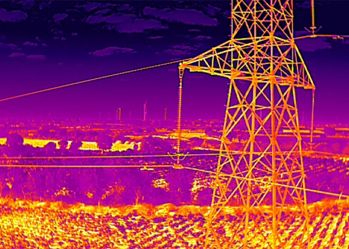
In India, this typically covers lines from 33kV sub-transmission up to 765kV extra-high-voltage (EHV) corridors. A drone flies a programmed route alongside or above the line, capturing RGB and thermal imagery at the component level insulator strings, arcing horns, vibration dampers, and conductor joints. Ground patrols can only assess what a lineman can see from below or reach by climbing; helicopter surveys move faster over distance but at lower resolution and higher cost per kilometre. Thermal imaging closes the gap between the two: a loose conductor clamp or a degrading insulator typically runs hotter than its surroundings well before it fails visibly, so radiometric sensors flag it while it is still a maintenance item rather than an outage.

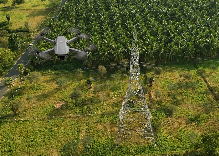
Drone inspecting high voltage transmission tower in India surrounded by agricultural land and coconut plantation
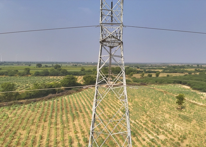
Aerial view of lattice transmission tower rising above farmland during drone inspection

Why Undetected Line Defects Are So Costly

India’s transmission network spans lakhs of circuit kilometres, much of it through terrain that is difficult or hazardous to patrol on foot forested corridors, hill sections, river crossings, and coastal stretches. Manual foot patrols cover only a few kilometres a day, and defects near the top of a tower are easy to miss from ground level.

Undetected problems compound quietly. A loose bolt or a corroding cross-arm doesn’t announce itself it shows up later as sag, misalignment, or a fault trip. SCADA and load-dispatch systems only flag a problem after it has already interrupted supply, by which point repair cost and downstream reliability impact are both higher than if the defect had been caught during a scheduled inspection.

There’s a safety dimension too. Live-line and climbing inspections put linemen at working height near energised conductors, and helicopter patrols carry their own operational cost and risk. Without geo-tagged, timestamped inspection records, utilities and EPC contractors are also left with a thinner audit trail to support maintenance planning, warranty claims, or reporting to CEA and PGCIL. Aerial drone inspection has become standard practice across several of India’s infrastructure sectors for exactly this reason — closing the gap between routine patrols and the defects that actually cause outages.

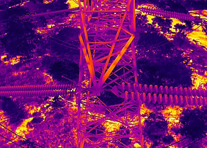
Radiometric thermal image of transmission tower and corridor showing temperature variation across landscape
Process

From Flight Plan to Defect Report: How Inspection Works

1

Pre-flight route planning

corridor mapping from tower GPS coordinates and existing right-of-way records, with the flight path segmented by voltage class and terrain.

2

Site risk assessment

DGCA airspace clearance, proximity checks to live conductors, and insurance and permission verification for the specific line and state.

3

Flight execution

In-house, DGCA-certified pilots fly RTK-enabled drones carrying radiometric thermal and RGB payloads along the programmed corridor.

4

Data capture

component-level imagery of every tower, insulator string, and conductor span, plus orthomosaic and, where scoped, LiDAR corridor data for clearance and vegetation analysis.

5

AI-assisted data processing & defect classification

AI-assisted anomaly detection flags candidate defects; an inspection engineer reviews each flagged image to rule out false positives from soiling, reflective glare, or normal load-related heating.

6

Defect report delivery

Component-level defect log with severity classification, GPS coordinates, thermal and visual evidence, and a prioritised maintenance list, accessible through Lesoko's project dashboard.

Component-Level Detection

Every Component Assessed on a Transmission Tower

Each drone flight captures component-level imagery across every part of the tower and corridor not just the conductor and insulator string.

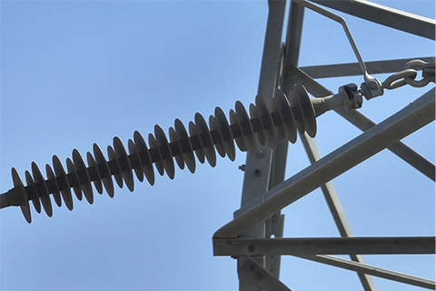
Long composite insulator string with disc sheds mounted at transmission tower cross-arm

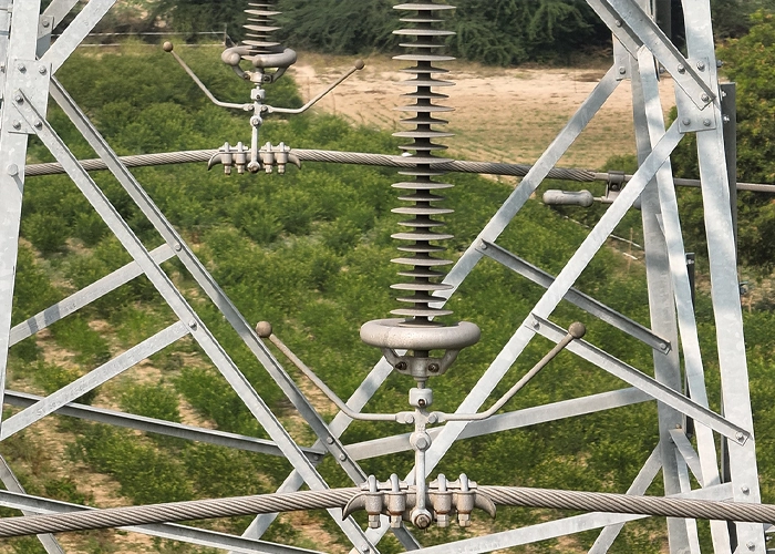
Insulator Strings

Contamination, mechanical stress, or ageing discs raise leakage current and flashover risk.
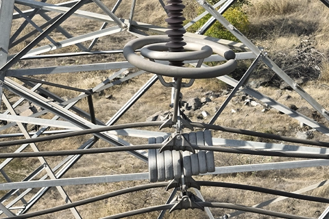
Corona control rings and connected hardware viewed from above at transmission tower peak

Arcing Horns

Corrosion or misaligned gap spacing weakens surge and lightning protection at the string.
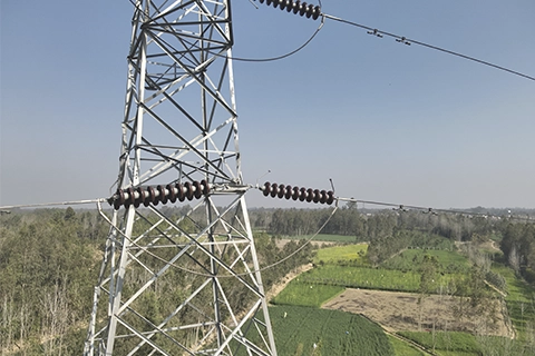
Transmission tower viewed from elevated angle showing insulator strings and conductor jumper connections

Jumper

Damage or burn marks on the conductor jumper loop create localised heating and arcing risk.
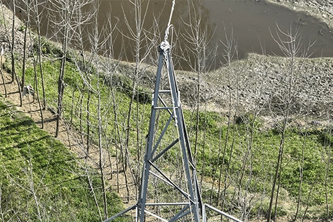
Aerial view of transmission tower apex with ground wire jumper loop above a pond

GW Jumper

A damaged ground-wire jumper breaks continuity in the tower's lightning protection path.
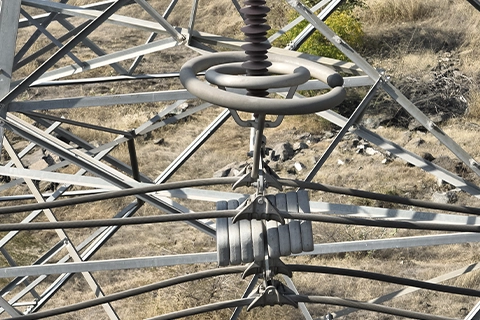
Corona control rings and connected hardware viewed from above at transmission tower peak

CC Rings

Damaged or misaligned corona control rings raise localised electrical stress and interference near hardware.
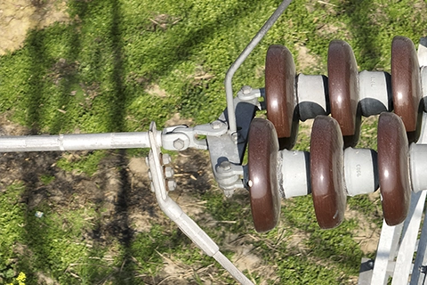
Strain insulator assembly with clamp hardware securing conductor at tension tower

Strain Clamps

Loosening or wear at the strain clamp risks conductor slippage and localised heating at tension towers.
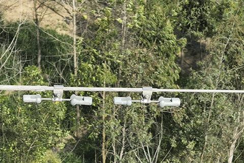
Vibration dampers clamped along a transmission line conductor above forest canopy

Vibration Damper

Displaced or damaged dampers accelerate conductor fatigue from wind-induced vibration.
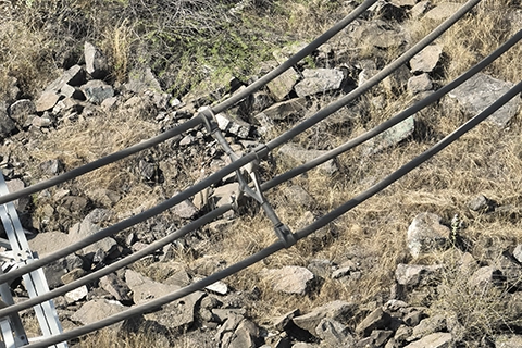
Bundle conductor spacer bridging parallel transmission cables over rocky terrain

Spacer

A damaged or missing spacer lets bundled sub-conductors clash under wind loading.
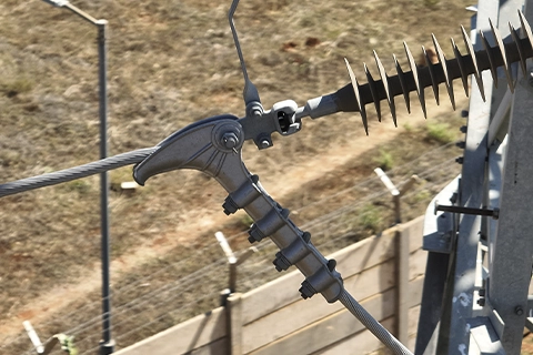
Close-up of an arcing horn and clamp hardware attached to a transmission line insulator

Cross Arm

Corrosion or bending of the cross arm reduces the load capacity supporting insulator strings and conductors.
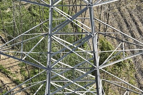
Aerial drone view looking down through the lattice cage of a transmission tower structure

Tower Body / Cage

Missing nut-bolts, corrosion, or a bent member in the lattice structure risks reduced load capacity.
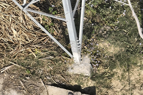
Transmission tower foundation leg set into concrete footing surrounded by vegetation

Foundation Leg

Vegetation encroachment, corrosion or footing erosion pose a long-term stability risk at the base.
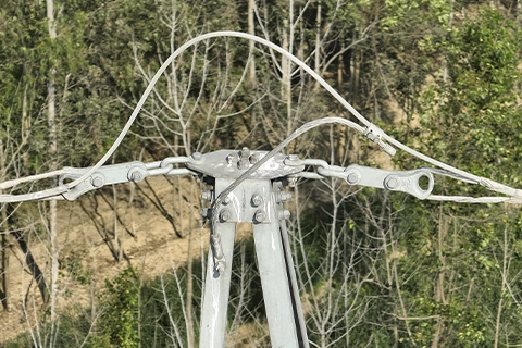
Ground wire connection loop at the peak cross-arm of a transmission tower

Earthing Wire

Corrosion or disconnection at the earthing wire weakens fault-current dissipation at the tower.
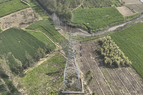
Bird's-eye drone view directly above a transmission tower base surrounded by farmland

Anti-Climb Fence

Damaged or missing fence panels at the base create an unauthorised-access and safety compliance risk.
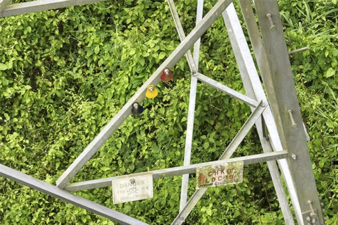
Danger warning tag and lock-checked tag on transmission tower member amid dense vegetation

Danger Sign

A missing or faded warning sign at the tower base is a site-safety compliance gap flagged during inspection.
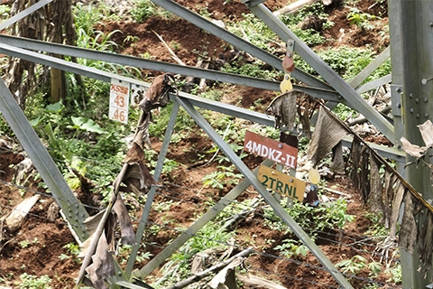
Tower identification tags hanging on transmission tower lattice member near ground level

Name Board

A missing or illegible tower ID board slows down asset tracking and maintenance dispatch.
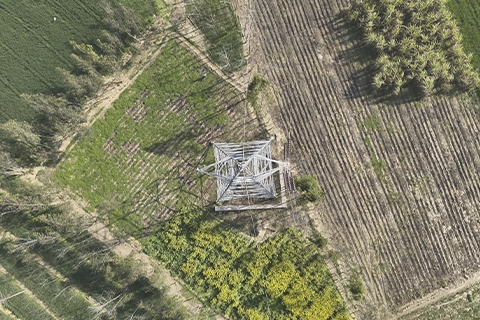
Bird's-eye drone view directly above a transmission tower base surrounded by farmland

Aerial Photography

High-resolution RGB capture of the full tower and corridor context right-of-way condition, vegetation encroachment and land use around each structure.
Methodology

Technical Methodology and Standards

Flight altitude and sensor resolution are set to achieve a ground sampling distance fine enough for component-level defect identification not just a corridor overview. Thermal sensors capture absolute temperature values at 0.05°C sensitivity, calibrated against an ambient reference, with average, maximum, and minimum readings recorded per component and benchmarked against its expected operating range.

Flights are scheduled within wind and visibility thresholds appropriate for stable imagery near live conductors, and thermal passes are timed against expected load conditions rather than early-morning convenience alone. Captured imagery is processed into a radiometrically corrected orthomosaic of the corridor, with AI-assisted anomaly detection followed by engineer review the review step is what filters out false positives caused by soiling, reflective glare, or ambient thermal noise. LiDAR survey, where scoped, adds centimetre-level accuracy for conductor-to-vegetation and conductor-to-ground clearance measurement. All inspection data is handled under project-based access control, with NDA terms available before a project begins.

Close-up of insulator string, arcing horns, and strain clamp hardware on a transmission tower cross arm
Thermal image of insulator strings on transmission tower cross arm showing temperature contrast

For new-build lines, Lesoko also performs post-erection, pre-stringing tower completion inspection verifying tower verticality and alignment, foundation bolt security, and the absence of missing or damaged members against design and safety standards, before conductors are strung. This uses the same drone-based, component-level methodology as operational line inspection, applied at the construction QA stage instead of the O&M stage.

Inspection practices are aligned to Central Electricity Authority (CEA) and Power Grid Corporation of India (PGCIL) transmission line maintenance guidance, with DGCA Drone Rules, 2021 as the baseline operational standard for every flight.

Thermal anomalies at a loose clamp or an ageing insulator often develop weeks before they produce a visible fault or trip a protection relay which is what makes a scheduled thermal survey a more sensitive early-warning signal than waiting on a SCADA alarm.

Who This Service Is Built For

State Transco & DISCOM O&M Teams Managing Multi-Circuit Corridors

Teams responsible for maintaining reliability across many kilometres and multiple voltage classes need consistent inspection data without disrupting supply to schedule around.

EPC Contractors Commissioning New 33kV–400kV Lines

Beyond operational inspection, Lesoko performs post-erection, pre-stringing tower completion inspection checking verticality, foundation bolt security, and structural completeness before conductors are strung giving EPC teams a documented baseline and clean handover record.

Private Transmission Licensees & IPP Grid-Connection Teams

Managing inspection vendors across several states is easier with one partner delivering consistent reporting, rather than coordinating separate regional contractors for each corridor.

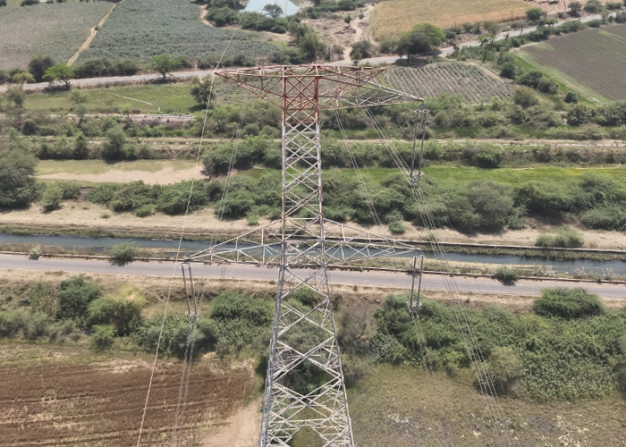
Aerial view of transmission tower with conductors spanning a road and canal crossing near farmland

Pan-India Deployment, 33kV to 765kV

Lesoko has completed transmission line inspection projects covering more than 1,500 km, including 440kV/220kV/765kV lines for Indigrid, 33kV/220kV lines for Hero Future Energy, 33kV/110kV/220kV lines for RSA Renewables, and 220kV lines for TNEB. Active project experience spans Odisha, Maharashtra, Tamil Nadu, Gujarat, Rajasthan, Karnataka, and Andhra Pradesh. Projects across South India mobilise from Lesoko’s Chennai head office; other states are served through pan-India crew deployment.

Pricing

What Determines Inspection Cost

Drone-based transmission line inspection is priced per project based on operational scope. There is no standard rate that applies uniformly across voltage classes, corridor lengths, and terrain types.

Aerial survey delivers substantially lower O&M inspection cost per corridor kilometre than equivalent manual patrol determined by corridor length, voltage class, and sensor combination while earlier defect detection reduces corrective maintenance costs and unplanned outage risk. To receive an accurate proposal, share your voltage class and corridor details.


Pricing variables that determine inspection scope and cost

Drone-Based Transmission Line Inspection in Action. See How We Detect Faults Across HV & EHV Lines

Proven Results — Case Study Widget
Proven Results
Real Projects.
Measurable Impact.
📍 Jhankarpali, Odisha · 132KV Single Circuit · Tension Towers

A 132KV single-circuit transmission corridor at Jhankarpali, Odisha was inspected across 5 tension towers. The inspection surfaced 19 defects across multiple component types — with vegetation encroachment dominating across foundation legs and critical structural hardware faults on Tower 5, including insulator deformation, missing nut/bolt, and arcing horn deposition. All defects were GPS-tagged with thermal and RGB image evidence per component.

Voltage
132 KV
Total Towers
5 Towers
Circuit Type
Single Circuit
Inspection Date
13 Feb 2026

Outcomes Achieved

19 total defects identified across 5 towers — 0 towers in good health prior to inspection
1 tower Defective · 4 towers Attention Required — full corridor flagged for maintenance
Insulator deformation on Tower 5 flagged for immediate replacement to prevent electrical leakage failure
Missing nut/bolt on Tower Body 1 escalated as Severity 3 — structural fastening risk identified
GPS-tagged report delivered in PDF + Excel with thermal image evidence per component

Defect Breakdown — All 5 Towers

Foundation Leg (V)
16 · 84%
Insulator (DF)
1 · 5%
Tower Body (BM)
1 · 5%
Arcing Horn (DP)
1 · 5%

Tower Health Summary

Good
0 towers
Attention Required
4 towers
Defective
1 tower
📍 Mogarale, Maharashtra · 33KV Double Circuit · Feeder Lines

A 33KV double-circuit transmission line at Mogarale, Maharashtra was inspected across 13 feeders over two days. The corridor carried significant thermographic anomalies — insulator temperatures across feeders ranged from 18.7°C to 40.6°C. A total of 154 insulator defects were identified, with a flashover event flagged on the VEL_F1 feeder requiring emergency corrective action. Per-insulator thermographic temperature data was delivered for all feeder strings.

Voltage
33 KV
Feeders Inspected
13 Feeders
Circuit Type
Double Circuit
Inspection Dates
30–31 Dec 2025

Outcomes Achieved

154 total insulator defects identified — 151 on primary feeders, 3 on MSETCL secondary lines
Flashover event on VEL_F1 feeder flagged for immediate emergency corrective action
8 towers Defective · 4 Attention Required · 1 Good across 13 feeders
Insulator temperature anomalies up to 40.6°C on Feeders 1 and 3 — enabling priority maintenance scheduling
Full per-insulator thermographic temperature log (min / avg / max) delivered for all feeder strings

Defect Breakdown — 154 Total Defects

Insulator (All types)
154 · 100%
Insulator Damage (D)
3 · Feeder 3
Flashover Event
1 · VEL_F1

Thermographic Temperature Range

Max Recorded
40.6°C
Average Range
28–35°C
Min Recorded
18.7°C

Tower Health Summary

Good
1 tower
Attention Required
4 towers
Defective
8 towers
📍 Tusura-1, Odisha · 132KV Single & Double Circuit · Tension Towers

A 132KV mixed single and double-circuit corridor at Tusura-1, Odisha was inspected across 34 tension towers over four days. The inspection uncovered 95 defects — the largest single-corridor defect count in this series. Arcing horn deposition (38) and foundation leg vegetation (42) dominated, with additional hotspot insulators, jumper deformation, and missing components spread across multiple towers.

Voltage
132 KV
Total Towers
34 Towers
Circuit Type
Single & Double
Inspection Dates
08–11 Feb 2026

Outcomes Achieved

95 total defects across 34 towers — 85% of towers require maintenance action
19 towers Defective · 10 Attention Required · 5 Good
38 arcing horn deposition defects flagged across double-circuit towers — surge protection at risk
42 foundation leg vegetation encroachments GPS-mapped for targeted right-of-way clearance
Hotspot insulators and jumper deformation on multiple towers prioritised for immediate replacement

Defect Breakdown — 95 Total Defects

Foundation Leg (V)
42 · 44.2%
Arcing Horn (DP)
38 · 40%
Jumper (H / DF)
8 · 8.4%
Insulator (H / DF)
7 · 7.4%

Tower Health Summary

Good
5 towers
Attention Required
10 towers
Defective
19 towers
Deliverables

What You Receive

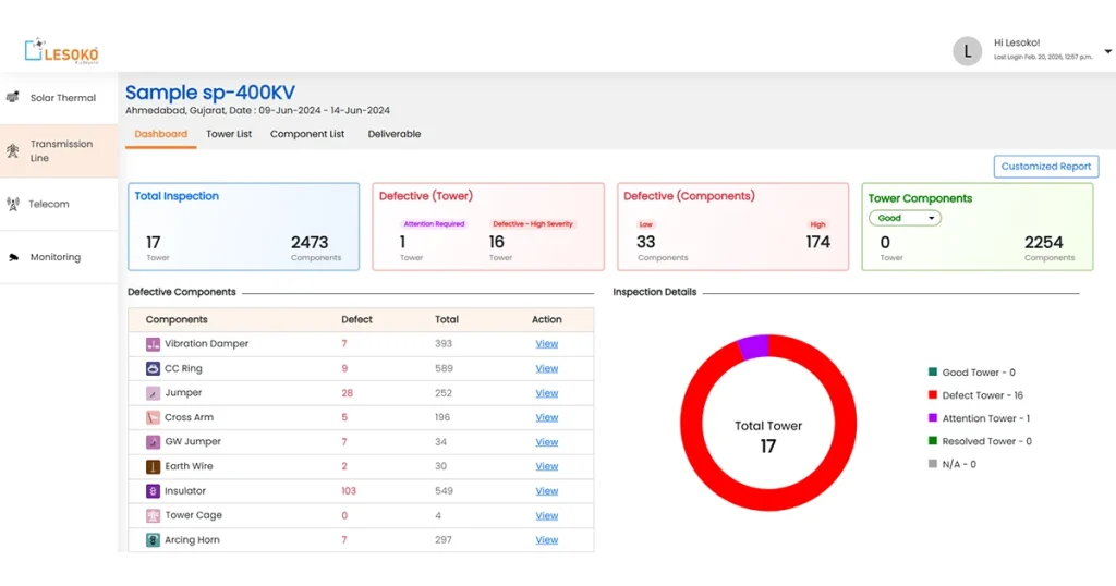
Lesoko drone inspection dashboard showing 17 towers 2473 components inspected with 103 insulator defects on 400KV transmission line Gujarat India

Summary Excel Report

Cumulative tower-wise summary with defect count per component, overall tower status (Good / Attention / Defective), and sortable data for maintenance planning.

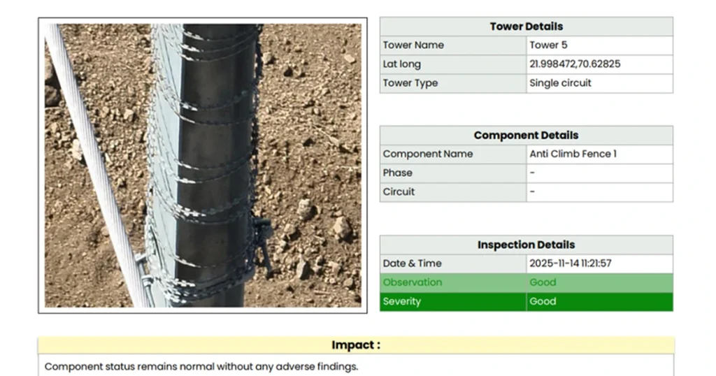
Lesoko transmission tower component inspection report showing anti climb fence condition assessment with GPS coordinates and severity rating for single circuit tower India

Tower Defect Report

Component-level defect sheets with GPS coordinates, photographs, thermal images, severity ratings, impact assessment, and specific recommendations per tower.

Lesoko transmission line inspection platform showing GPS-mapped tower list for 400KV line in Ahmedabad Gujarat India

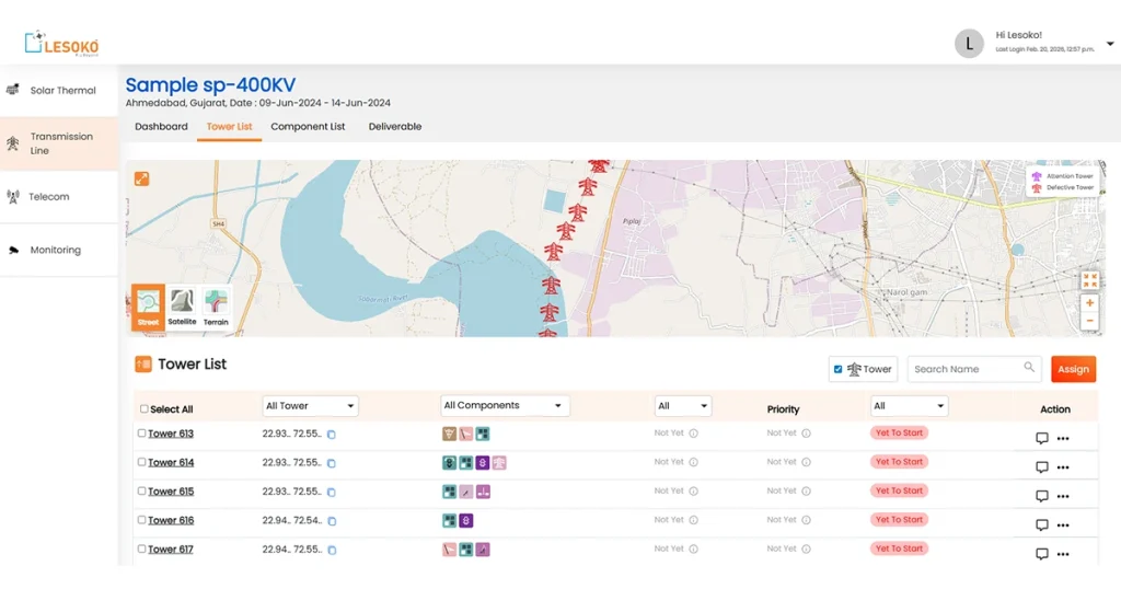
GPS Asset Map (GIS)

Precise tower location data in GIS format for network-wide visualisation. Colour-coded markers by severity. Exportable for existing asset management systems.

Lesoko thermal imaging inspection report showing Severity 3 insulator defect on transmission tower with temperature readings min 27.9 max 30.5 degrees single circuit line India

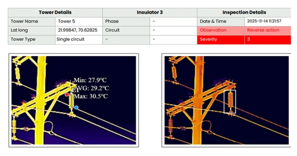
Live Dashboard Access

Real-time project dashboard with interactive map, component status navigation, thermal image viewer, and downloadable reports. All data accessible on any device.

Request an Inspection Proposal for Your Transmission Assets

Free · No obligation · Quote in 24 hours
 

Phone/ Whatsapp

+91 78457 26375/ 7845726374

Email Us

sales@lesoko.in

Head Office

2nd Floor, Chettinad Chambers, P.S.Sivasamy Salai 1st Street, Mylapore, Chennai, Tamil Nadu 600004

Get Your Inspection Quote

Frequently Asked Questions

Yes. Drone inspection is performed at a safe standoff distance from energised conductors, so lines stay live throughout no outage window or load-dispatch coordination is needed. This is one of the main safety and operational advantages over live-line climbing inspection.


Detailed inspection is generally recommended at least once a year for EHV lines (220kV and above), and at least every two years for sub-transmission lines (33kV–132kV), in line with CEA and PGCIL maintenance guidance. Lines through high-risk terrain, dense vegetation, or cyclone-prone coastal corridors may need more frequent surveys, and a post-storm inspection is standard practice after extreme weather.


Drone inspection detects insulator damage and contamination, arcing horn misalignment, missing nuts and bolts at lap and butt joints, missing step bolts, corrosion on tower hardware, thermal hotspots at joints and connectors, and vegetation encroachment within the right-of-way much of it before the defect is visible from the ground.


Cost depends on voltage class, circuit length, terrain accessibility, tower density, and the sensor combination required. Request a quote based on your line’s voltage class and length.


Thermal (radiometric infrared) imaging detects abnormal heat signatures at conductor joints, clamps, and insulator hardware. Lesoko’s sensors capture absolute temperature values at 0.05°C sensitivity, so a poor connection can be flagged during a scheduled inspection rather than after a trip.


LiDAR captures a centimetre-accurate 3D model of the line corridor, used to measure conductor-to-ground and conductor-to-vegetation clearance against regulatory minimums, and to map vegetation encroachment along the right-of-way more precisely than photo interpretation alone. See Lesoko’s dedicated LiDAR survey service for corridor-wide clearance mapping.


Yes. All flights are conducted by Lesoko’s in-house, DGCA-certified pilots not subcontracted operators. Lesoko has completed more than 5,000 transmission-line flights with zero recorded crash incidents.


No. Inspection is carried out on energised lines during normal operation, with no outage window or load-dispatch coordination required.


Yes. Lesoko’s project dashboard shows a tower-by-tower breakdown of defects, priority, and resolution status, along with an interactive GIS map view and on-demand Excel/PDF report generation not just a one-time static PDF.


It’s a construction-stage inspection carried out just before conductors are strung, checking tower verticality and alignment, foundation bolt security, and that no structural members are missing or damaged, against design and safety standards. Lesoko performs this using the same drone-based component-level methodology as its operational line inspection service.


Scroll to Top